Series Wiring
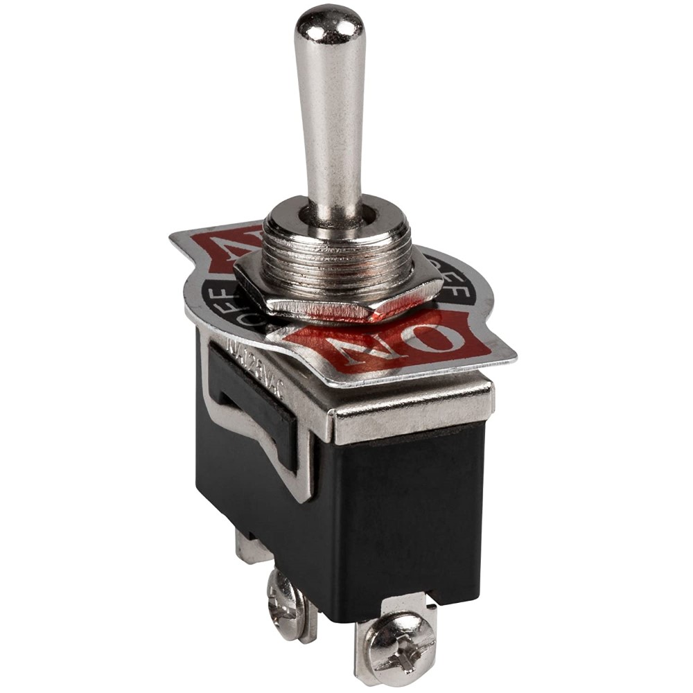
When two pickups are wired in series, the output of one is connected to the ground of the other. The outputs are directly additive, there is no loading effect as with parallel wiring. You get noticeably more output, and usually a much fuller sound. Two pickups may be wired in series with a standard [ON-OFF-ON] switch, available at any hardware store.
It is possible to 'daisy chain' as many pickups as you want like this, but for practical purposes, three single coils is the limit, more than that becomes boomy and harsh. This is why humbuckers generally do not sound good in series - the two coils in each pickup are already in series, putting the pickups in series puts all four coils in series, it's just overload. On the other hand, humbuckers often sound better in parallel than single-coils, it lightens them up a bit, whereas single coils in parallel can become overly thin - the 'quack' sound that the Strat is so famous for. I'd rather roar than quack, especially on a bass.
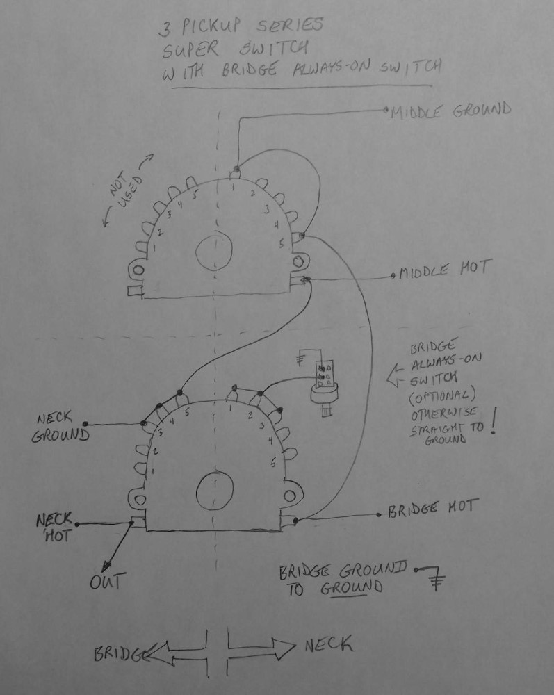
Here is a 5-way 'super switch' (4p5T!) wired for 3 pickups in series. This is something you never see, which is a shame, it sounds awesome. Gone is the thin quack of the combination positions, replaced by a much bigger tone that actually exceeds the single selections. Also shown is a push-pull pot wired to make the bridge pickup 'always-on', allowing for the two forbidden combinations.
Pickup switching with series wiring is not so much a matter of selecting the pickup(s) you want, but de-selecting the ones you don't want. You can't do this with an ordinary Strat switch ( another reason why Fender went parallel ) but you can do it with a modern 'super switch'. A super switch is really 4 independent 5-way switches ( or poles ) that move as one, like two ordinary blade switches ganged together. For series switching, you use one pole per pickup, so in this case, one pole is unused. For each position on the switch, you remove some pickup(s) from the chain by shorting its output to its own ground, turning it into an inert loop. This preserves the path to ground for the entire chain, while effectively silencing that particular pickup. So for position 1, you would short out the middle and bridge pickups, and only the neck would sound. Etc. Note that you short each pickup to its own ground, not to the main ground.
You can also install a push-pull switch to one of the tone knobs which defeats the 'de-selector' for the bridge pickup. ( Confused yet? ) This allows for the forbidden combinations that the 5-way switch won't give you: neck and bridge, and all three. In a parallel world, you would use the switch to do the opposite to get the same effect: it would enable the bridge pickup independently of the blade switch.
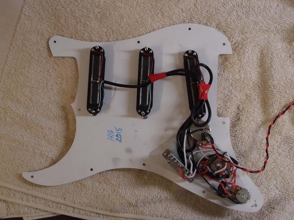
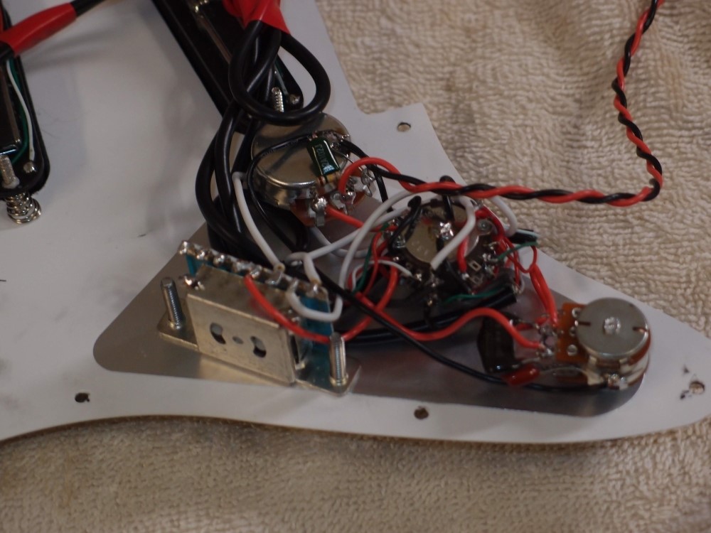
A caveat about the super switch is that it is physically bigger, wider, and deeper than a standard switch, and will only fit into a full-thickness body. You can see the size of it in the photo. Many of the Squier bodies you will find, such as the Bullet line, are too thin to take the switch I used. Even with this full-thickness body, I had to Dremel a shallow pit for the switch to sit in, but that is mainly so that it is not shorted-out by the conductive shielding. I used a double thickness of electrical tape in the bottom just to be sure.
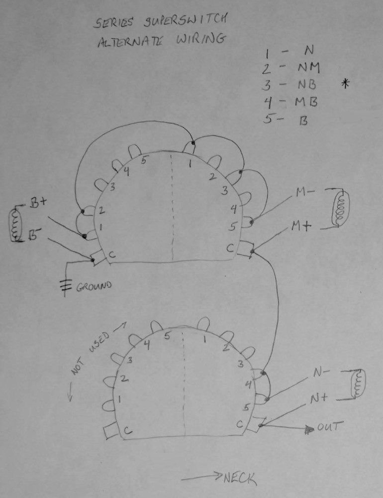
This modification substitutes the neck-bridge combination for the middle pickup, giving: 1-5: N-NM-NB-MB-B. I installed this in the piccolo bass. ( I violated my no-humbuckers-in-series rule, but for this application, every bit of extra oomph is welcome, and they're pretty lightweight humbuckers anyway. )
It's a pretty good trade, neck-bridge for middle. With single-coils, this is not a humbucking combination, so there is no gain or loss in that respect. Sound-wise, the new combination is somewhere between the two standard combinations. The differences are fairly subtle, but you get a much smoother transition from position to position than you would with the normal setup. Note that all of this and a bit more is achievable with my previous super-switch wiring using one extra switch. This has the advantage of being perhaps more 'natural' and easier to use.
To understand the circuit, try to imagine that the switch is not there, but the jumpers are. Now, you simply have all three pickups connected in series:
ground --> (B- B+) --> (M- M+) --> (N- N+) --> output
Think of the ground as sort-of source or 'signal', which it is not really, but it helps. The 'signal' passes through all three pickups to the output. If the 'signal' goes through the pickup, then that pickup is active, otherwise, it is silent.
The super-switch is simply 4 separate switches ganged together. Each switch position connects that numbered lug to its common. So if you study the individual switches you can see, for example, that in position 1 the bridge pickup is looped onto itself, + and - connected together, while still passing ground through for the middle pickup. Or in other words, the ground 'signal' short-circuits around the pickup. Since lug 2 is jumpered to lug 1, it has the same action. Lugs 3,4, and 5 are not connected, so in these positions, ground goes through the bridge pickup instead of around it.
Any pickup that is shorted like this will be silenced. Taken to the extreme, connecting the ground to the output will silence the whole chain. So the trick in deriving this wiring is to provide a suitable ground to the output of each pickup whenever you don't want it to sound. There is actually a lot more obvious way to draw out the equivalent circuitry. This drawing is modified from that to show optimized physical connections on the switch. Related pickup leads attach close together, and no lug has more than two connections for easier soldering. Any shielding can be grounded to the switch body, which can then be grounded itself.
A drawback of series wiring is that if two pickups are not a hum-canceling pair, putting them in series makes them hum even louder, as everything is additive.
Danelectro Wiring
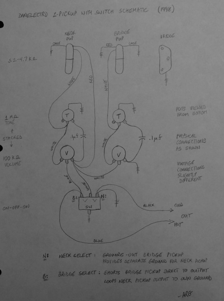
This is the standard series wiring of a 2-pickup Danelectro. Talk about unintuitive, what on earth is that switch doing? Remember, that is an ON-OFF-ON switch like you'd find at the hardware store, not an OFF-ON-OFF switch as is typically found in a guitar. I love Danelectros for defying all conventions of 'luthiery' and being great instruments in spite of that, or perhaps because of that.
Note that the volume and tone controls are individual for each pickup, and upstream of the switch. The key here is the series wiring. You don't have to use the individual concentric controls typically found on Danelectros.
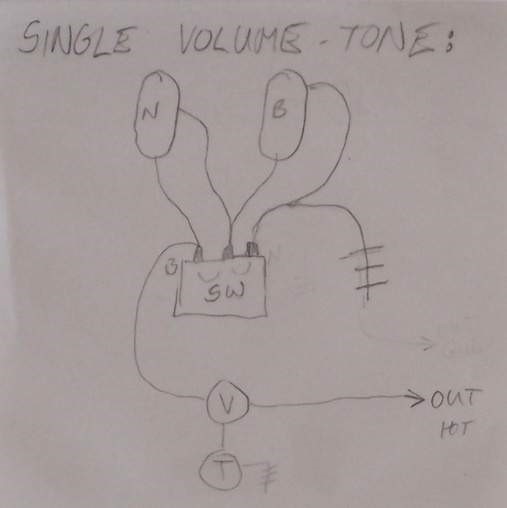
Here is the same Danelectro wiring simplified to the bare minimum, with single downstream volume and tone as is typical in most guitars.
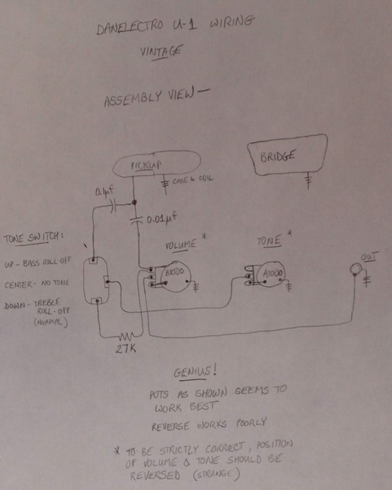
This is the ingenious wiring of a Danelectro single pickup guitar. The switch selects between no tone control, treble control, or bass control, and the whole circuit is so effective that you don't even miss a second pickup. The switch has no apparent effect if the tone control is zeroed.
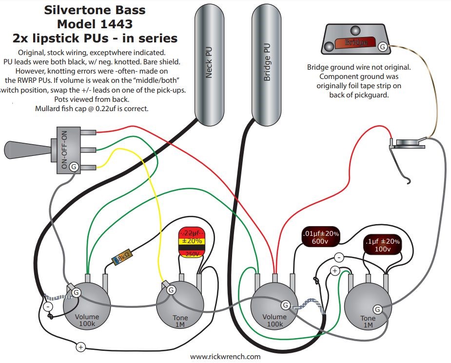
I believe my diagram above was actually drawn from a reissue. Here is a diagram drawn from an original 1960s Danelectro bass. It is basically the same, except for using three different tone capacitors and the addition of a stray resistor on the neck pickup, probably to balance the volume with the bridge pickup. This is the first time I have ever seen that done on a factory instrument. That third capacitor looks almost like a stage coupling capacitor in an amplifier. Nathan Daniel was a trained electrical engineer, not a luthier.
I have taken apart old Danelectro guitars, but never a bass. As I recall, the guitars are exactly like my diagram above. I suspect the extra resistor and capacitor in this diagram are particular to the bass. To be honest, I can't figure out what the 0.01uf capacitor is for. If anyone knows, please leave a comment.

Questions or Inquiries?
Just want to say Hello? Sign the .