Piezos & Buffers
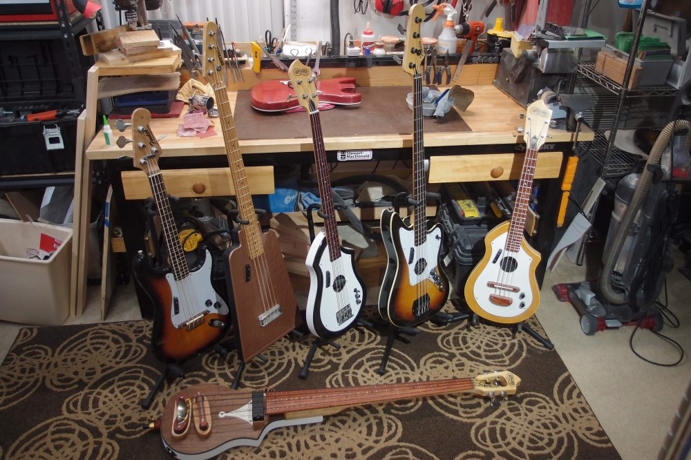
These are all of my piezo creations, so far. All of them utilize a version of the original single-transistor CafeWalter piezo buffer. He encouraged me to use his newer two-transistor version, but I never did get it to work. The simpler circuit works just fine, and I am a great fan of simple things that work.
Piezos generate electricity when they are deformed - bent or compressed. Simply shaking them does little or nothing, especially at the low frequencies. Installing a piezo on a bass is tricky. No body mounting I ever tried was successful, you need tight coupling with the strings, which means a bridge mounting. Even then, it is tricky, you must get the force on the piezo element right, too much or too little and you get poor response. Take note of the break-over angles on the saddles above. It doesn't take much.
For wiring purposes, treat piezos like capacitors - they sum in parallel, subtract in series. Therefore multiple piezos should always be wired together in parallel. Phasing is also important. Piezo materials are very brittle and easy to break. If you want to fool with piezos, especially button-type, get extras. You will break a few before you are done.
You can stick a piezo almost anywhere on a guitar and it will pick up something. Without a high-impedance buffer, you will get no bass. On a guitar that doesn't matter much, but on a bass it is paramount. For good response on a bass, you must have solid coupling with the strings, and an impedance buffer.
Types of Piezos
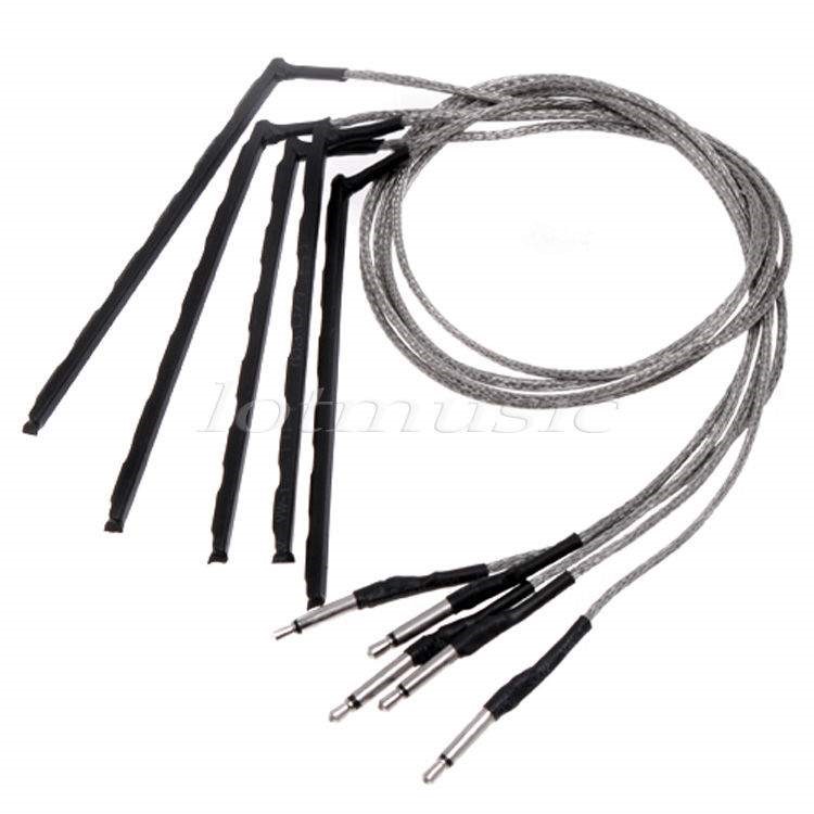
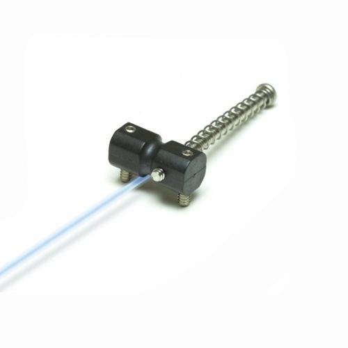
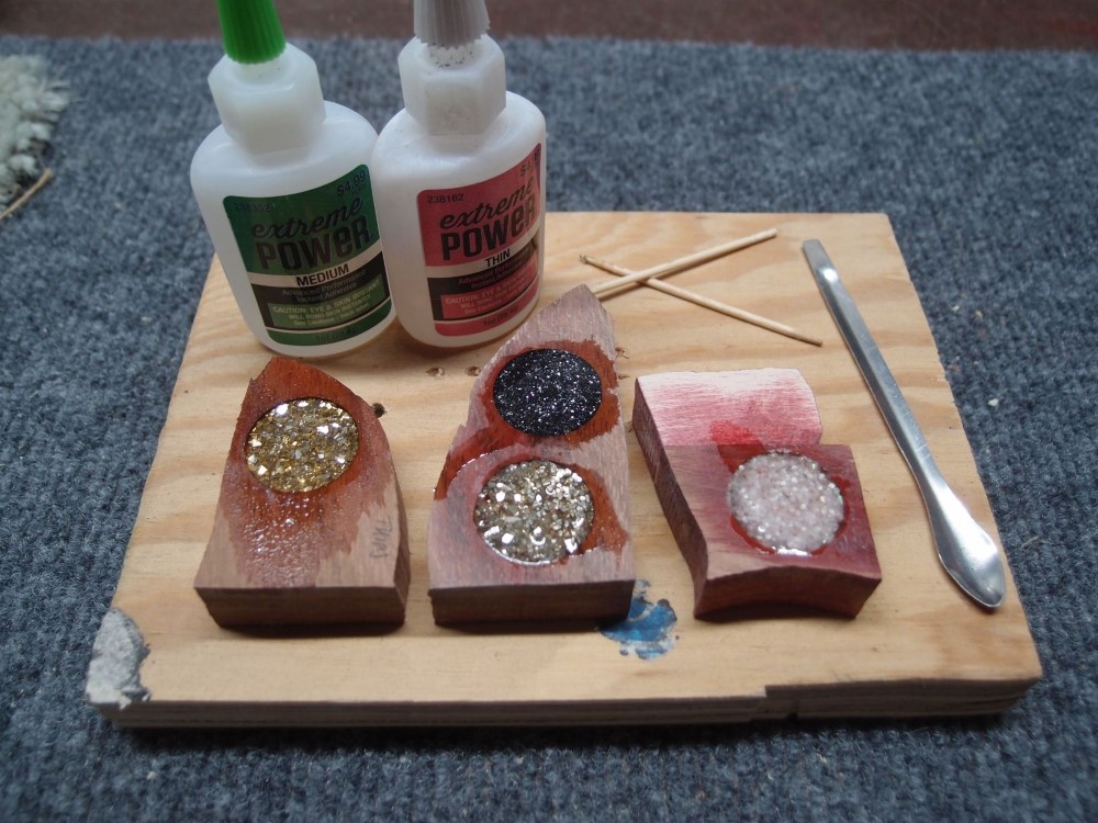
Under-saddle rod piezos for acoustic guitar. The plug is 2.5mm; I usually just cut it off. Larger versions are available for bass, but these work fine as long as they cover the whole string spread. In my experience, all piezos have basically the same frequency response, although they can vary in output level. These are fairly tough. As little as a buck each.
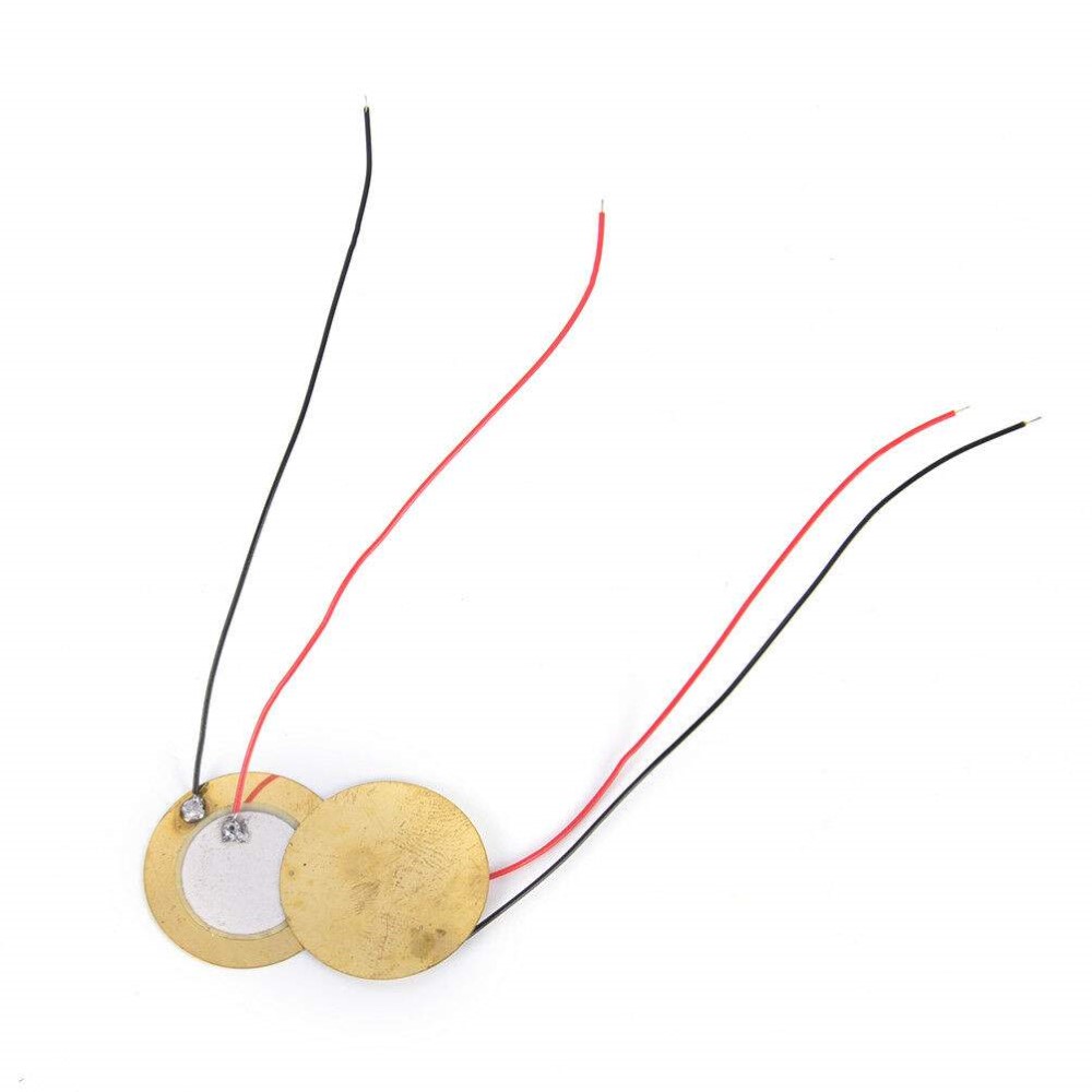
Button-type piezos, available in many sizes. You can carefully trim away the excess brass plate to fit in tight spots. These are easily broken. Less than a dollar each.
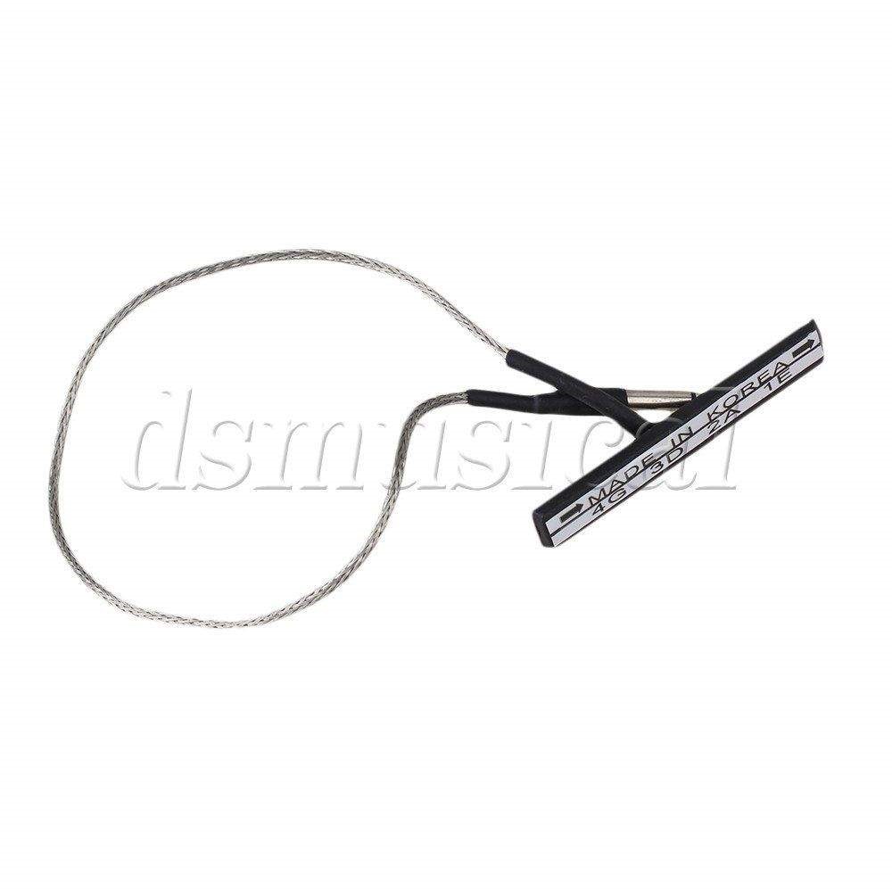
Violin-type piezo - looks really promising, but do not use. This has just a small element on one side, low and unbalanced output. A few dollars each.
GraphTech Ghost piezo saddle, Fender-style. These are sold in sets of four or five for about $100. GraphTech has a full range of piezo products, including buffers, not cheap.
You can also buy piezo rod and wire in bulk and make your own, but it's not really worth it.
Piezo Buffers
Piezos are strange things, with very high impedance, or "Z", and it is accepted practice to use active electronics to tame their bad qualities. An active buffer circuit will match the piezo's high-Z on the input side, and reduce it to a nice amp-friendly low-Z signal on the output side.
If you want to play with peizos, high-impedance circuitry is a must. The GuitarFuel/Artec circuits are ideal for this use, but many cheaper Chinese circuits are not. You can buy suitable impedance buffers online, but they tend to be very pricey. I build my own, to this design, which is simple and works very well.
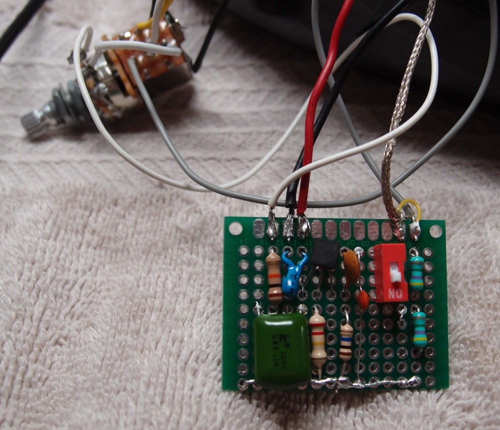
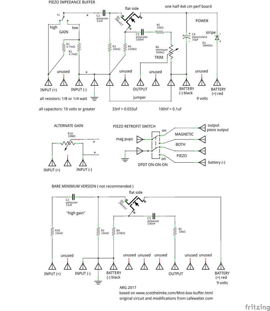
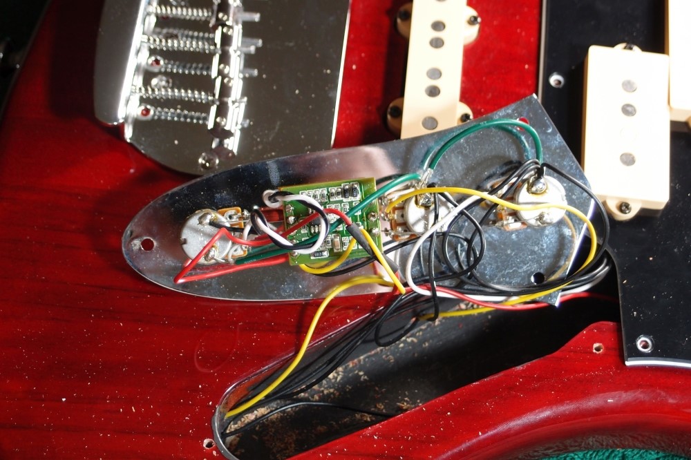
This is my version of Walter's buffer circuit, which can easily be built on a small piece of perforated circuit board as shown. The upper version has some additions, like reverse voltage protection, noise filtering, and input and output adjustments. The lower version is the bare minimum circuit. Commercially available buffer circuits are ridiculously priced, and really no better. The diagram can also be used as a physical layout for the circuit.
All the parts are from eBay; for a few dollars, you can get enough parts to assemble a dozen circuits. You'll also need a fine soldering iron and a heat sink for soldering the transistor, a small alligator clip will do. I use a strong pair of reading glasses from the Dollar Store.
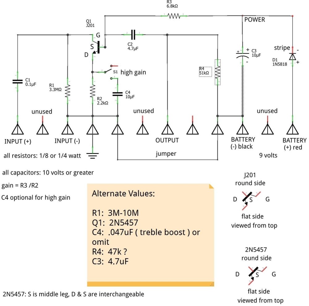
This pre-amp design might be a good alternative to the impedance buffer above, but I have never tried it.
An alternative to a dedicated buffer is a set of active tone controls with a high-impedance input. Artec and GuitarFuel make appropriate and reasonably-priced circuits that will take a piezo directly. I don't know about Belcat and many other inexpensive Chinese setups, many are not suited for piezos unless you use an outboard impedance buffer in front of them.
Note that if you go this route, you cannot mix piezo and magnetic pickups in front of the high-impedance circuit, which will destroy the high impedance for the piezo. You can mix the output of a piezo buffer with magnetic pickups, but you cannot mix the inputs.
I strongly recommend using an easily accessible battery box for any onboard electronics, so that you can install a battery only when you are actually playing the instrument and remove it the rest of the time. 9-volt batteries are guaranteed to leak and should never be left installed in any device that is not actively in use. This is true of all batteries, but 9-volts are by far the worst. Avoid Duracells, all sizes.
Piezo Installations
This is the bridge and piezo installation on the Audiovox. The Strat is almost identical. It uses an integrated saddle/sensor as is common on acoustic basses and easily found on eBay. That rests in a structure that adjusts for height and intonation, although intonation is unimportant on these instruments. If you disassemble one of these piezos, you'll find a fairly ordinary rod-type piezo element under the saddle.
The tailpiece on the Strat is actually mounted in the tremolo hole.
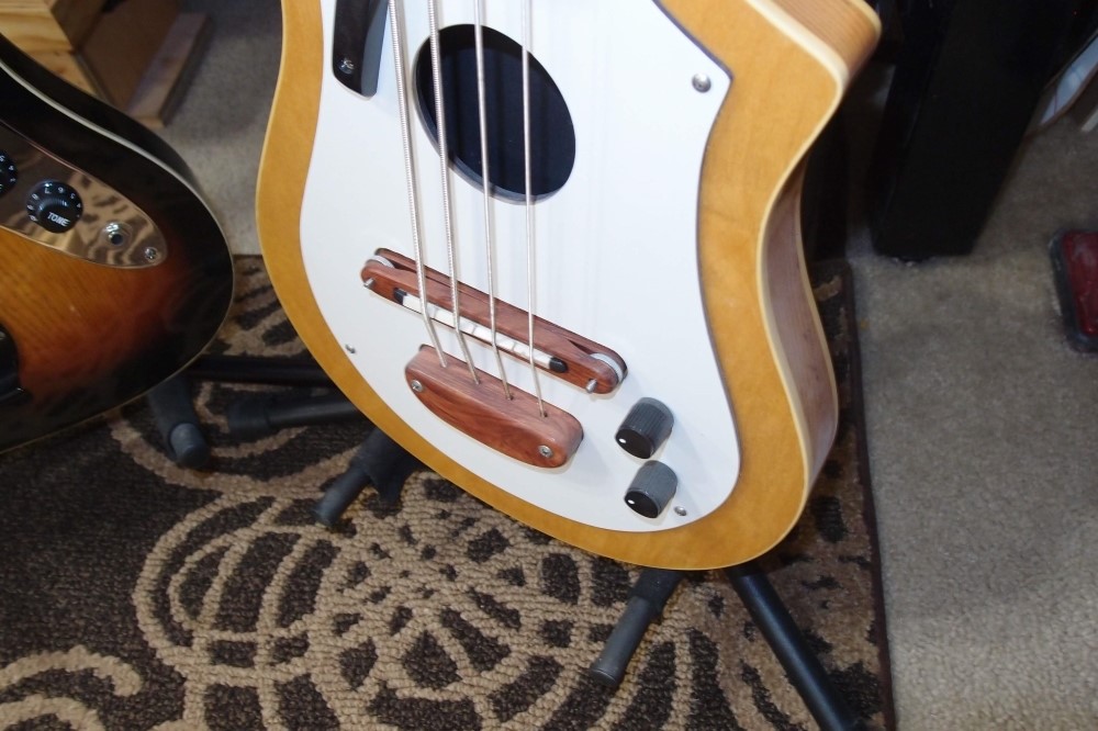
This is the piezo on the Cowbell. A sort-of Fender-style bridge structure adjusts for height and intonation. It holds a standard acoustic guitar under-saddle rod piezo in an aluminum channel under a phenolic saddle. Fender acoustic bronze strings. This bass was built specifically as a testbed for this bridge.
All of the above are very inexpensive installations, made from scrap materials. All work very well.
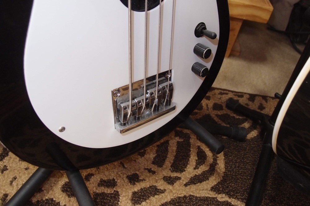
This is the bridge on the hollow-body Jazzmaster, with individual GraphTech Ghost saddles. Each one has a wire that goes down through a hole in the bridge plate, where they are collected together in parallel. These work great, but they are very expensive compared to my home-brew installations, which sound just as good and were more fun to create. For variety and dead-battery situations, this bass has a backup magnetic pickup.
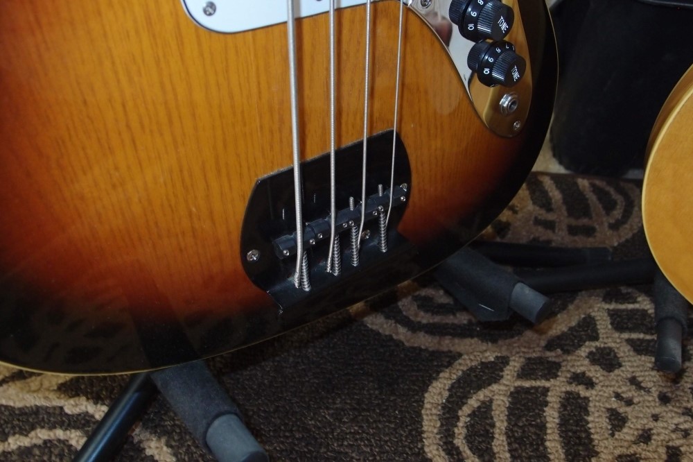
This is the fretless Audiovox. I tried many different installations on this instrument before I found one that works. A number of different body mountings all resulted in low output and poor frequency response, especially at the low end. The big pickguard hides a lot of damage.
Finally, I mounted a pair of button piezos under the bridge. Buttons cost just pennies. The result works as well as any of the other basses here. You can't just wedge them under there, that works no better than anything else I tried. If you can figure out what I did from the picture, good for you, otherwise I'm not saying.
This bass has a soundhole-mounted magnetic pickup as insurance against never finding a good way to mount the piezos. Fortunately, eventually, I did.
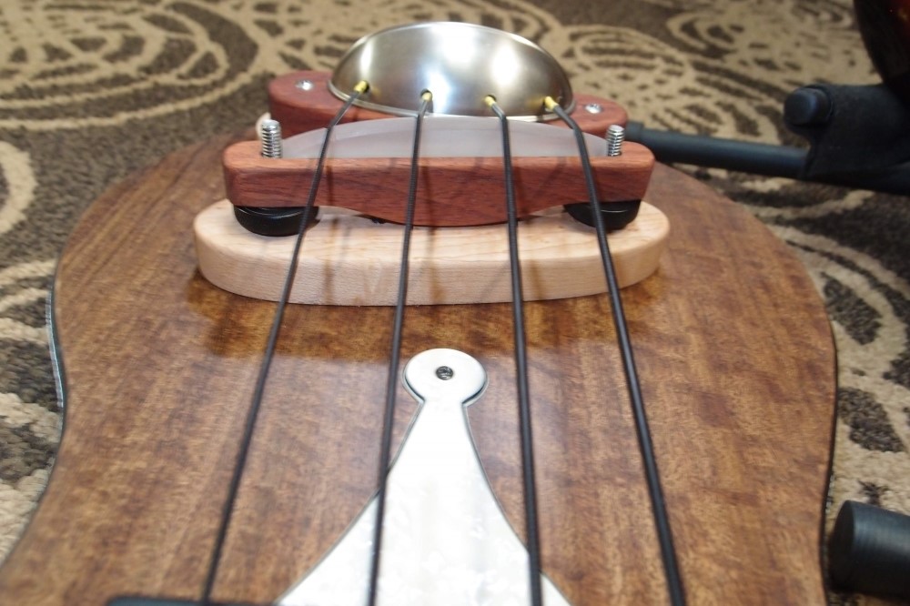
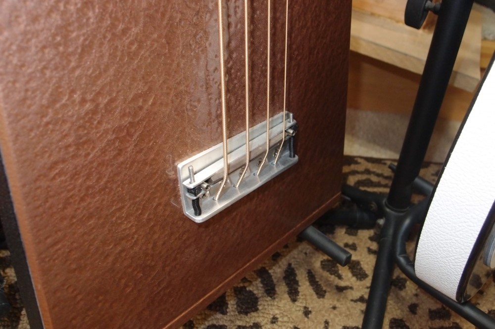
This is the piezo bridge on the upright. It is a scaled-up version of the uke bridge design, with a pair of rod piezos under the acrylic saddle. The wires run straight down into a cavity in the maple base, then into the body. Response is strong, I actually had to dial it back to match the magnetic pickup. I originally tried a pair of violin piezos that worked very badly.
And that's all I have to say about that ...
Questions or Inquiries?
Just want to say Hello? Sign the .