Passive Distortion
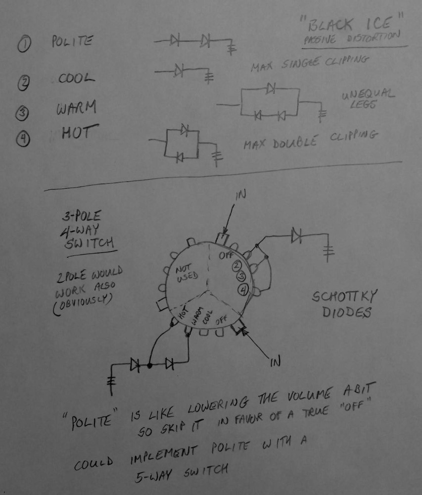
This is a selectable onboard passive distortion circuit using clipping diodes wired to ground. All solid-state 'artificial' distortion circuits, no matter how expensive, have something like this at their core. Instead of requiring power, this circuit uses the output of the pickups themselves and therefore should work better with higher output pickups. It uses a 2-pole 4-position rotary switch to select various combinations of diodes for different degrees of distortion, or none. You could also select one of the diode combinations and wire it to a push-pull switch for a single level of distortion, or even wire it to a separate 'volume' control to control the resistance to ground and therefore the amount of distortion. The diodes cost pennies. I have yet to actually try this one, but when I get back to building six-strings, I definitely want to.
Each 'pole' of a switch is actually a separate switch. A 3-pole switch is actually 3 separate switches on one shaft that move together. The diagram shows a 3-pole 4-position rotary switch instead of a 2-pole 4-position, which is instructive: you can always use a bigger switch and just 'waste' the extra capacity. Why would you want to do this? Switches can be used for many different applications, and there is often little difference in price between different models. Stocking the 3-pole switch gives me more flexibility in what I can do later, even if, as in this case, I waste part of it.
This circuit only works well with extremely high-output or "hot" pickups. With most pickups, it does little or nothing.

Questions or Inquiries?
Just want to say Hello? Sign the .