Double-Acting Truss Rod
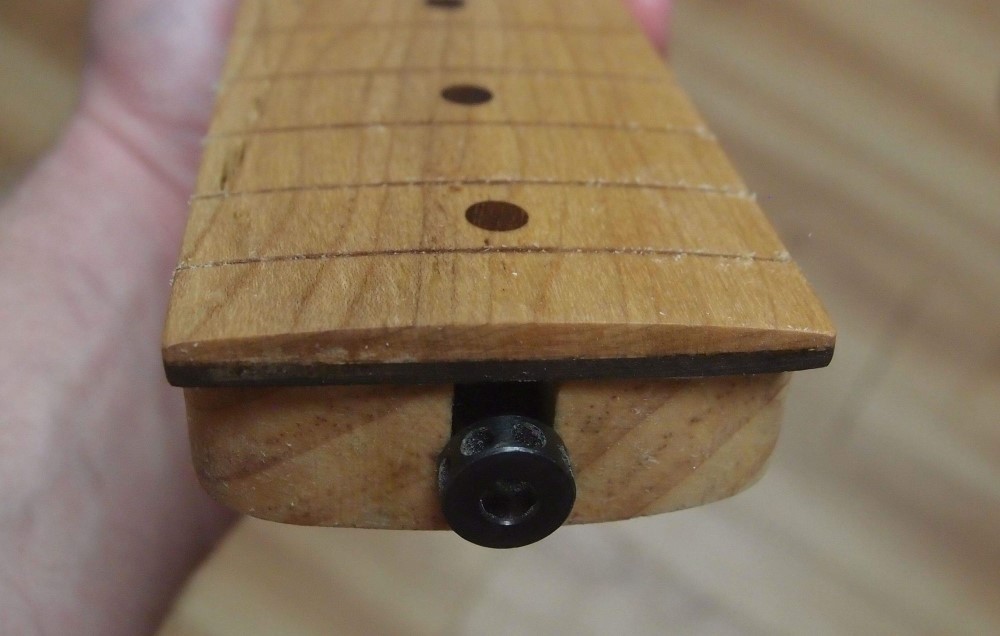
This is a spoke nut version, for use at the neck heel.
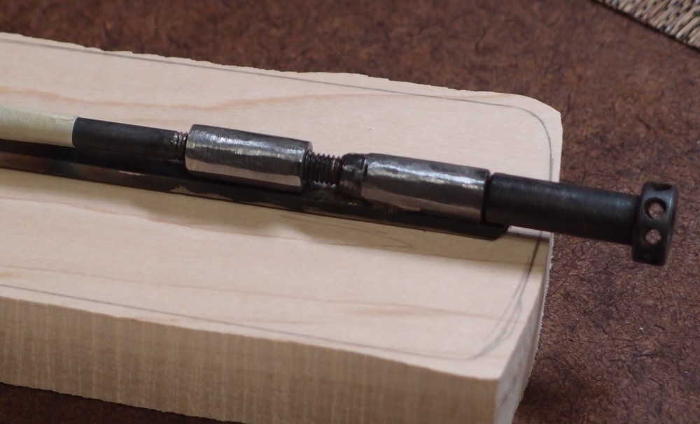
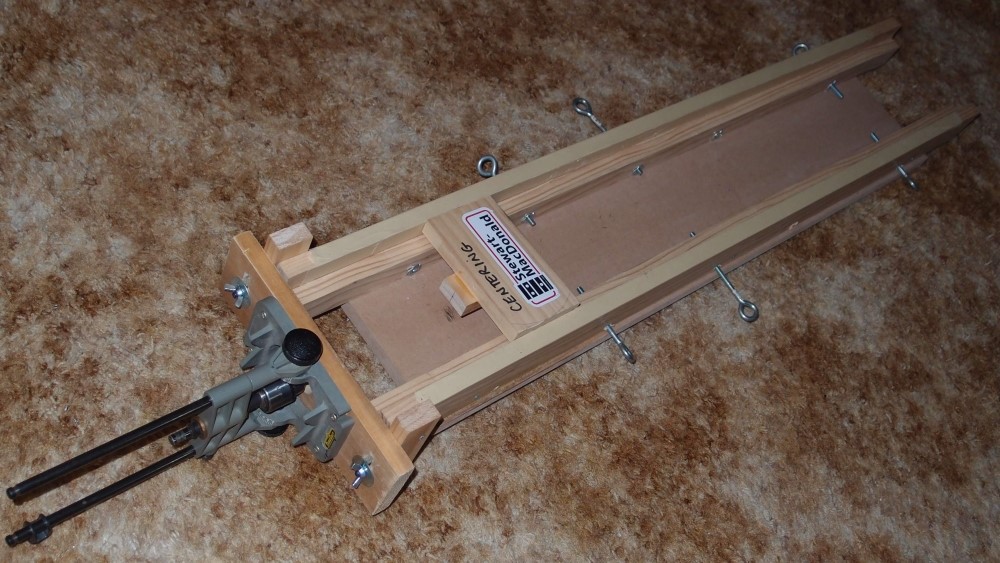
Here is a variation intended to adjust at the headstock rather than the heel, although it would work fine there too. I substituted a 1-1/2" 10-32 SS cap-head bolt for my usual spoke nut and threaded shaft. It is captured the same way, in a drilled-out coupling nut with a ground-down hex nut. The rod itself is 48" 3/16 rod steel, bent back on itself. Both coupling nuts are grooved on the attaching surface to hold the round rod. This greatly simplifies alignment and assembly, and the cap-head bolt eliminates one solder joint. All parts from my favorite luthiery supply shop, Home Depot.
This mechanism is capable of about 1/4" of pull, and 1/8" of push, which so far has been more than enough. The slot for the rod will be routed right through the heel of the neck, so that the rod can be pushed out if ever need be, like a Rickenbacker.
Note that with this design there is no need to stick with 10-32 threads; you could use 10-24, metric, or anything else available that you can cut a thread for.
This was the apex of my truss rod development before I decided that it was just too complicated to build, and switched to something much simpler. However, if you would like to attempt this, here are the old instructions:
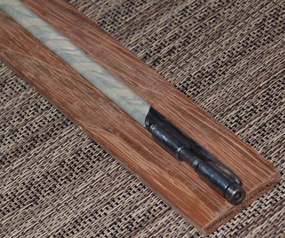
This is my best truss rod design and the end of my truss rod evolution. This truss rod adjusts at the heel with a MusicMan-style spoke nut ( $5 from StewMac ) although you could use whatever nut you like. The result is the strongest possible neck that is easy to adjust without removing the neck or needing any special tools. I use an old drill bit for a lever.
Also, the rotating assembly is kept as compact as possible, and the required thread-cutting is reduced to an absolute minimum by using a store-bought bolt as the core for the adjusting mechanism.
This design places all the bulky components in the neck heel, where there is plenty of room, as opposed to the headstock-end, where the neck is thinnest. One of the reasons so many Gibson necks break is their insistence on hollowing out the smallest part of the neck to fit in the truss rod adjusting mechanism.
The top end of this rod is as compact as it possibly could be. The rod is installed only after the neck is completed, as the protruding spoke nut head would interfere with finishing. Normal tension locks it in place, but it can be removed at any time by simply slacking it. This is a double-acting rod, it can push or pull, one of the only ones that can use a spoke nut.
In the photo, the rod is upside-down. At the bottom is a piece of steel bar stock. Above that is a piece of steel rod. The two are brazed together at the other end. Alternately, you could bend a double-length piece of round rod back on itself, the bend taking the place of the far braze joint. I've made them that way too. The big advantage to doing it that way is that the round rod is cheaper and more readily available than the rectangular bar. Finally, you could also use 2 single-length pieces of rod and braze them together in place of the bend, but I think keeping the round pieces aligned would be tricky, and I have never tried it. None of this makes any difference in the function of the finished product.
A properly-made silver braze joint is actually stronger than a weld, so don't worry about that. Nowadays, spot welding is done cheaply by machine, whereas silver brazing is a lost art. This is a bit more complicated than sweating a plumbing joint, but if you can do that, you can do this. The most difficult part is keeping everything precisely aligned.
Assembly is fairly straightforward, using an ordinary propane torch and high-strength solder. Propane is in theory not hot enough for this solder, but the parts are small enough that you can get away with it and not need expensive hi-temp gas. It just takes longer, hold the flame on the parts until they glow nice orange. Flux is essential. I doubt ordinary plumbing solder is strong enough, but I've never tested that.
There are lots of instructional videos on this sort of brazing on the YouTubes, so I'm not going to go into detailed instructions on brazing. You can also use the torch to burn the zinc coating off the parts where necessary.
MATERIALS
- 1x 10-32 spoke nut, or whatever else you prefer ( StewMac )
- 1x 2" 10-32 bolt ( hardware store )
- 2x 10-32 coupling nut ( hardware store )
- 1x 10-32 hex nut ( hardware store )
- 1x double length 3/16" mild steel rod ( hardware store
-- OR --
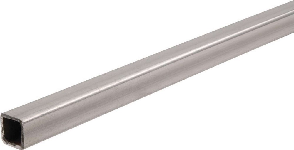
1x single length 1/4" x 1/8" mild steel bar ( mcmaster.com ) plus
1x single length 3/16" mild steel rod ( hardware store )
-- OR --
2x single length 3/16" mild steel rod ( hardware store )
do not use threaded rod - it is not strong enough
- high strength silver brazing solder ( eBay )
- high temperature brazing flux ( eBay )
TOOLS
- tape measure or long ruler
- container of water to quench hot parts
- propane torch and fire extinguisher, just in case
- file or bench grinder
- drill or drill press, with metal drill bits
- 10-32 thread-cutting die set
- 3-in-1 or other suitable oil
- small vise-grips to clamp parts together
- hammer ( for bent-rod version only )
- bench vise with a small anvil ( a large vise-grip can serve in a pinch )
- cement garage floor, patio, or sidewalk makes a suitable workspace
- heavy long pants and leather shoes to guard against solder drips
- pliers, to handle hot parts
- always wear eye protection
CONSTRUCTION
1. Cut the head off a 2" 10-32 bolt, thread one end 1/4" into the spoke nut, and tack in place by flowing a bit of solder into the threads.
2. Drill out another 10-32 coupling nut to 3/16" and insert the bolt through it. The bolt should rotate freely but snugly in the coupling nut. A drill press with a drill vise is the best thing for this, but a drill and a large vise grip will get the job done. Always use plenty of oil when drilling metal.
3. Thread the 10-32 hex nut onto the bolt, snug up against the coupling nut, and tack in place by flowing a bit of solder into the threads. You want to be very neat in this step, just a touch of solder to fix the hex nut to the bolt, without soldering the whole assembly solid. The flux will probably run inside and bind the assembly, but you can break it loose with a wrench.
4. You now have the coupling nut free to rotate on the bolt, but captured between the spoke nut and the hex nut. Carefully grind the hex nut down to a smaller diameter than the coupling nut, so that it will rotate without interference in the final assembly. Trim the bolt so about 3/4" is exposed beyond the hex nut, and re-dress the threads. This is now the Adjusting Mechanism.
5. If you are using the bar and rod construction as shown, follow steps 6A-6D. If you are using the double-length bent rod construction, follow steps 7A-7G.
6A. Cut about 6 10-32 threads on the end of the rod, and thread 10-32 coupling nut on about 3/16" and tack in place by flowing a bit of solder into the threads. The coupling nut is then ground down to a minimal profile all around. Note that the coupling nut is not attached to the bar underneath, nor does it rotate.
6B. Align the coupling nut of the Adjusting Mechanism on the bar and braze the two together. A small vise grip can serve as a clamp. Again, take care not to get excess solder on the rotating parts and bind them, minor binding from the flux can be freed with a wrench.
6C. Thread the free end of the bolt about 3/8" into the other coupling nut. You want to leave an empty space inside the nut for the bolt to go in, and you want enough extra threads inside to back it out a bit as well.
6D. Cut the truss rod to the desired length and braze the two free ends together; I use a joint of about 3/4" length. Go to Step 8.
7A. Heat the rod in the center until it glows and fold it over on itself. Hammer the bend until it is tight. This may take more than one session with the torch to get everything straight. There should be no bulge when it is finished.
7B. Figure out how long the entire truss rod should be, from the face of the spoke nut to the other end. Subtract the length of the spoke nut, and cut one end of the rod to that length. Clamp the Adjusting Mechanism to the cut rod.
7C. Thread a second coupling nut about 3/8" onto the Adjusting Mechanism bolt. Mark the other end of the uncut rod to overlap about 3/16" with the coupling nut and cut. Remove the Adjusting Mechanism.
7E. Cut about 6 threads on the end of the rod that you just cut. Thread the second coupling nut about 3/16" onto the rod, and tack in place by flowing a bit of solder into the threads.
7F. Thread the Adjusting Mechanism bolt about 3/8" into the other coupling nut. You want to leave an empty space inside the nut for the bolt to go in, and you want enough extra threads inside to back it out a bit as well.
7G. Align the coupling nut of the Adjusting Mechanism on the long end of the rod and braze the two together. Again, take care not to get excess solder on the rotating parts and bind them; minor binding from the flux can be freed with a wrench.
8. File or grind the Adjusting Mechanism to a nice profile as in the photo. Clean up all rough edges. Put a drop of oil on the rotating parts where they mate. I wrap the rod in masking tape against rattles, but that is entirely optional.
INSTALLATION
A suitable channel for either style of this truss rod can be made with a 1/4" router bit, preferably round-bottomed, but not essential. This leaves 1/32" clearance on either side of the rod. The channel should be just deep enough to contain the rod. A 3/8" bit is used to widen and deepen the heel area for the Adjusting Mechanism, again, preferably round-bottomed. The truss rod channel is routed right out the end of the heel - no difficult end-drilling. The resulting opening is largely covered by the spoke nut. My truss rod channel routing jig makes all of this easy.
Cut the channel in multiple shallow passes, test fitting until the rod just fits. You want the channel to be as shallow as possible, especially at the thin end of the neck. Back-filling a too-deep channel will result in a neck that is weakened and destined to fail - better to scrap it early than replace it later.
When gluing the fingerboard onto the neck, run the truss rod in and out of its channel repeatedly to wipe away any glue squeeze-outs that would dry and interfere with installation later. You don't want to have to hammer the rod into the neck! Wipe off off any glue with a damp rag, and repeat until the rod comes out clean. Don't install the truss rod until the glue is good and dry, otherwise, any residue may bind it.
You could also route the end of the neck and fretboard beyond the last fret to recess the head of the spoke nut into the neck. This obviates the need to notch the body for the protruding nut. Either way works the same, I think sinking the nut into the neck looks odd.
NOTES
Truss rod length does not have to be very precise. I make mine so the head end falls somewhere between the string nut and the first fret. Ending the rod under the first fret is probably your best bet, especially if the neck is very fine. Plus or minus half an inch is good enough. Cut the channel a little longer than the rod.
Instead of cutting threads, you could drill out a short portion of the coupling nut to receive the rod directly, and braze the two pieces together. That would save on work and tooling, but I just don't think a joint like that would be very strong; I've never tried it and don't intend to.
You could build a similar and much simpler single-acting rod with a single drilled-out coupling nut. I'll leave it up to you to figure out. For a real quick custom-length truss rod, buy a long cheap rod on eBay, cut it to length, and braze the cut ends back together. This is the fastest way to make a custom truss rod, but you don't get an option as to the adjusting nut.

Questions or Inquiries?
Just want to say Hello? Sign the .